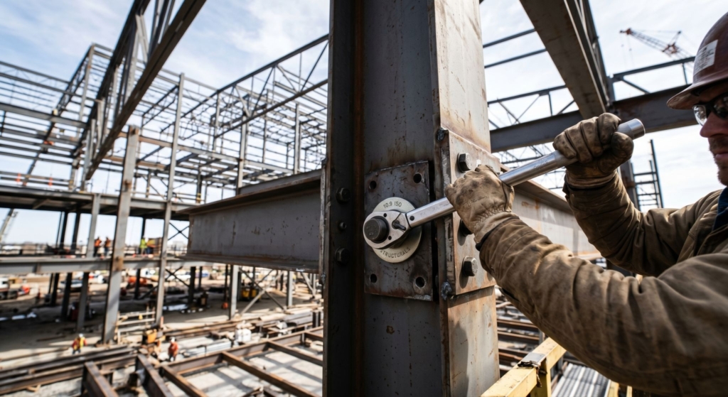
Bolted connections form the operational baseline of steel structures. They assemble in the field, disassemble for inspection, and submit to ultrasonic preload checks on the bench. Unlike a weld, a bolt can be retightened, replaced, or audited individually. In practice, a bolt’s actual service capacity rarely matches its catalogue value.
This article covers seven factors that determine the working strength of a bolt in a steel structure: material grade, preload and installation method, joint geometry, loading mode, fatigue, corrosive environment, and temperature. Each is examined against the active code base (Eurocode 3, AISC 360, ISO 898-1, EN 14399) and quantitative data drawn from open sources.
1. Material Grade and Metallurgy
The ceiling on bolt capacity comes from the ISO 898-1 grade designation. A grade 8.8 bolt has a minimum f_ub of 800 MPa and yield strength f_yb of 640 MPa, a ratio of 0.8. Grade 10.9 raises f_ub to 1000 MPa, and grade 12.9 reaches 1200 MPa. The bolt steel is typically medium-carbon or low-alloy (35Cr or 42CrMo for grades 10.9 and 12.9), quenched and tempered into its specified strength band.
Tensile resistance under Eurocode 3 EN 1993-1-8 follows F_t,Rd = 0.9 × f_ub × A_s / γ_M2, with γ_M2 = 1.25. The 0.9 factor accounts for stress concentration in the first engaged thread. The stress area A_s is computed from the mean thread diameter and pitch, not from the nominal shank diameter.
Grade 12.9 delivers the highest theoretical capacity. That same strength brings the failure modes addressed later under the environment.
2. Preload and Installation Method
Preload converts a joint from bearing-type to friction-type. Without it, load transfers through shank shear in the hole plus plate bearing. With it, force is held by friction across the faying surfaces. EN 1993-1-8 Category C (slip-resistant ULS) requires preload to EN 14399, where the nominal clamping force F_p, C = 0.7 × f_ub × A_s. For an M24 grade 10.9 bolt, this works out to 247 kN.
Preload is not directly observable in service. The gap between target and actual clamping is what calculation methods for bolt strength need to close: not the nominal F_p, C, but the residual force on the interface after every installation loss.
Sandia 2010 tests measured a preload scatter of 10 to 35 percent against the target with a torque-controlled wrench. Yield-controlled tightening drops scatter to about 10 percent, which VDI 2230 captures through a tightening factor α_A of 1.6 for the torque wrench versus 1.1 for yield control. Embedding (microplastic flattening of surface asperities at each interface) consumes another 1 to 7 µm per interface. For an M12 bolt, this costs about 12 percent of the preload. For M4, up to 38 percent.
A separate failure path opens when a shear-loaded joint actually slips. Under the Junker mechanism, transverse load cycles drive the bolt to back off through its own thread, preload decays, and the bolt then fails by fatigue at roughly 3,000 cycles.
3. Joint Geometry
Plate bearing resistance is verified separately from bolt resistance: F_b, Rd = k1 × α_b × f_u × d × t / γ_M2, where f_u belongs to the plate (not the bolt), d is the nominal bolt diameter, and t is the plate thickness. The α_b coefficient depends on edge distance in the direction of load. Typical minimum requirements under EN 1993-1-8 are 1.2d₀ for edge/end distance and 2.2d₀ for pitch in the load direction.
In long bolt rows, a reduction factor β_Lf < 1 applies once the connection length exceeds 15d. Shear flow is no longer uniform along the row, so the first and last bolts carry a disproportionate share.
Where the shear plane cuts the bolt matters through the α_v coefficient. If shear passes through the unthreaded shank, α_v = 0.6 for grade 10.9. If it passes through the threads, α_v = 0.5. The 17 percent difference depends on a single drafting decision and is routinely missed in hand calculations.
4. Loading Mode
EN 1993-1-8 splits bolted connections into five categories by load type. Categories A, B, and C cover shear with different preload requirements: A allows bearing-type without preload, B prohibits slip only at serviceability (SLS), and C prohibits slip at ultimate (ULS). Categories D and E carry tension, with D permitting snug-tight assembly and E requiring full preload to EN 14399.
When shear and tension act together, Eurocode requires an interaction check: F_v, Ed/F_v, Rd + F_t, Ed/(1.4 × F_t, Rd) ≤ 1.0. The 1.4 in the tension denominator reflects that preload is already embedded in the pure tensile formula and should not be penalized twice.
Flanged joints add prying action. The lever effect amplifies actual bolt tension by 10 to 40 percent over the externally applied force. AISC 360 publishes explicit prying formulas, and EC3 routes the same physics through its T-stub model.
5. Fatigue
Under EN 1993-1-9, bolts in tension (prying included) sit in detail category 50 MPa. That is the Δσ_C value at two million cycles, well below comparable values for parent plate material. The drop is driven by stress concentration at the thread root, where the notch factor runs from 4 to 10.
VDI 2230 sharpens this further. Reversing stress amplitude in a bolt with infinite-life requirements should stay below roughly 10 percent of its static tensile capacity. A grade 12.9 bolt rated for 1200 MPa under monotonic load is effectively limited to about 120 MPa of stress range for endurance.
A 2024 modelling study ran the same flanged connection with and without a 1 mm gap between plates. Without the gap, accumulated Miner damage came out to D = 5.61 × 10⁻⁶ over design life. With the 1 mm gap, the same joint reached D = 3.03 against the limit of 1.0. A millimeter of geometric mismatch shifted fatigue life by seven orders of magnitude.
6. Corrosive Environment and Hydrogen Embrittlement
High-strength bolts with UTS above 1000 MPa (grades 10.9 and 12.9) fall into the hydrogen embrittlement risk window. The BCSA 2022 technical note states the position plainly. Grade 12.9 should be excluded from structural connections. Grade 10.9 is acceptable only under controlled surface treatment, with electroplating ruled out and hot-dip galvanizing kept under tight thermal control.
Stress corrosion cracking follows the same physics on a slower clock. Atomic hydrogen diffuses into the zone of maximum tensile stress at the thread root, accumulates, and initiates a crack. Time to failure can run from months to years, and entry into this regime is typically tied to contact with marine atmosphere or industrial condensate.
Galvanic corrosion develops across dissimilar-metal pairs (a stainless bolt in a carbon steel plate, or the reverse) once an electrolyte is present. Atmospheric corrosion then erodes thread cross-section under sustained load, and fasteners in exposed structures consistently rank among the most environment-sensitive components in an assembly.
7. Temperature
Under fire, bolt capacity drops faster than the plate steel it joins. The ASCE 2020 study records a grade of 10.9 at 40 percent of room-temperature strength by 600°C, falling to about 5 percent at 800°C. Grade 8.8 follows the same trajectory on a slower decay curve.
Cold-climate applications (North Sea offshore, Arctic platforms) push carbon-steel bolts toward the ductile-to-brittle transition. For grade 8.8 and above, DBTT generally sits below minus 40°C. ISO 898-1 does not specify low-temperature toughness directly, so critical projects add a Charpy requirement at service temperature or call up EN 14399-3 K-class certification.
Closing
Grade sets the ceiling, not the working capacity. Between the catalogue f_ub value and the real margin in a joint sit installation accuracy on preload, plate and hole geometry, loading mode including prying, fatigue endurance, environmental state, and temperature range. Each factor is verified separately under EN 1993-1-8 and the adjacent parts of Eurocode 3, and each carries its own partial safety factor. A single missing coefficient in a single formula is enough to push the joint outside its design envelope.