Industrial automation systems rely on precise, reliable control of outputs—from motor contactors and solenoid valves to alarm systems and indicator lights. The QY-45Y3-Q8W32 industrial digital output module serves as a critical bridge between programmable logic controllers (PLCs) and the physical devices that drive manufacturing, HVAC, and process control operations. This comprehensive guide walks engineers, technicians, and automation integrators through everything needed to successfully deploy and maintain this versatile module.
Understanding the QY-45Y3-Q8W32 Module
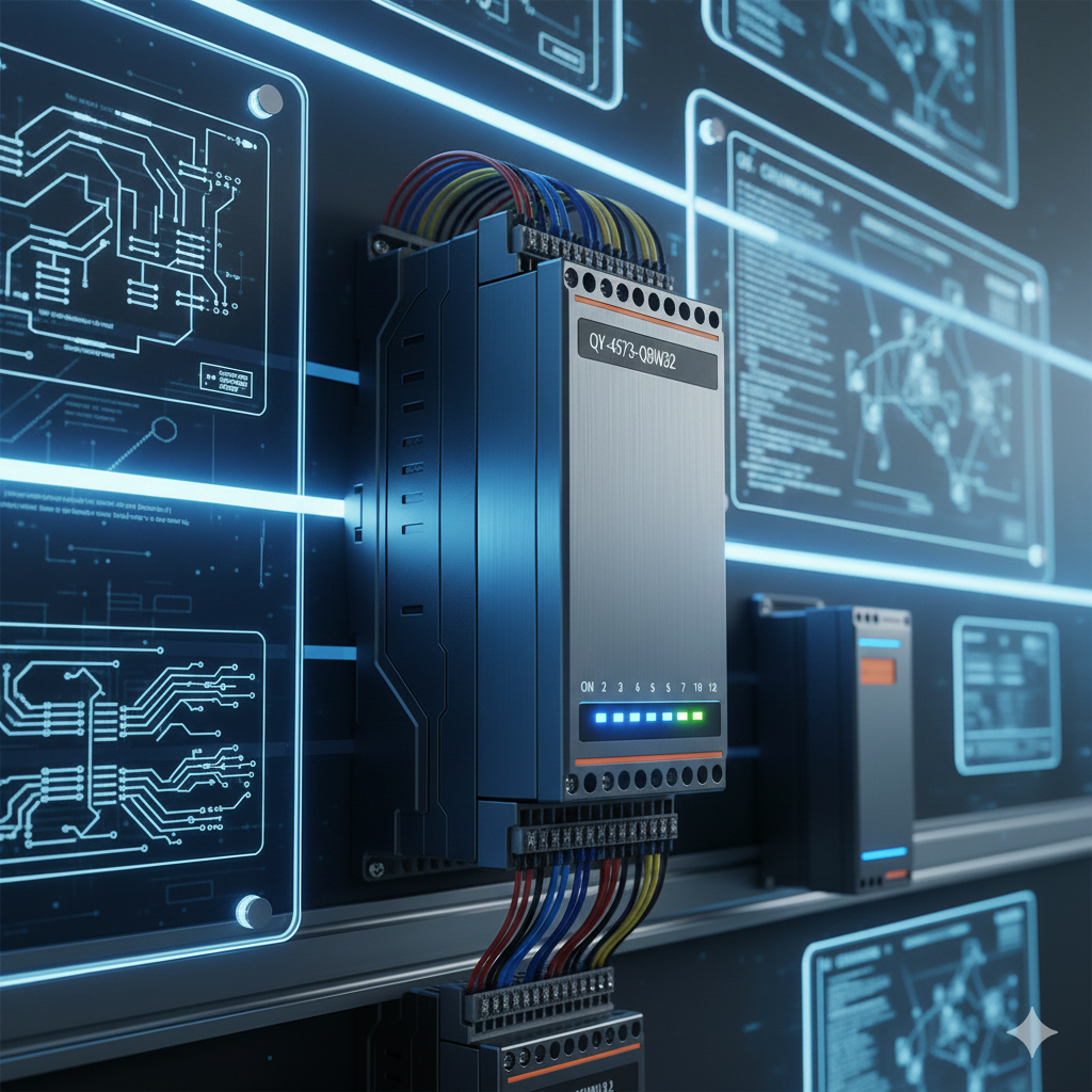
The QY-45Y3-Q8W32 is an industrial-grade digital output module designed to interface between control systems and field devices. In automation environments, digital output modules translate software logic into physical actions—switching motors on and off, activating warning lights, controlling dampers, or triggering alarms. This module excels in demanding industrial settings where reliability, speed, and electrical protection are non-negotiable.
Core Capabilities and Technical Features
The module offers flexible channel configurations with 8, 16, or 32 output channels depending on the specific model variant. Each channel can independently control a separate device or circuit, providing the scalability needed for both compact machines and complex production lines.
Response time is particularly impressive, with high-speed switching occurring in under one millisecond. This rapid response enables precise timing for applications like packaging machinery synchronization, elevator door control, or high-speed sorting systems where delays would cause operational issues.
Electrical isolation protects both the central processing unit and other system modules from voltage spikes and electrical faults originating in the field. This isolation acts as a firewall, preventing problems with one output circuit from cascading through the entire control system.
Built-in overload and short-circuit protection safeguards the module itself and connected equipment. When excessive current is detected, protection circuits activate automatically, preventing damage and simplifying troubleshooting. Each output channel features its own status indicator LED, providing immediate visual feedback on which outputs are active and making diagnostics straightforward even without specialized test equipment.
Real-World Applications Across Industries
Factory automation represents one of the most common deployment scenarios. The module controls actuators that position workpieces, motor contactors that start and stop conveyors, and indicator lights that signal production status to operators.
In HVAC systems, outputs manage dampers that regulate airflow, heaters that maintain temperature setpoints, and fans that circulate conditioned air. The module’s reliability ensures comfort systems operate continuously without manual intervention.
Elevator control systems use digital outputs for door mechanisms, floor indicator signals, and safety interlocks. The sub-millisecond response time proves essential for the precise timing required in vertical transportation.
Packaging machinery, conveyor systems, and automated warehousing depend on coordinated outputs for sorting gates, diverters, and position-dependent actions. Water treatment facilities use outputs to control pumps, dosing systems for chemical injection, and alarms for fault conditions.
Pre-Installation Planning
Success begins before the module leaves its packaging. Verify that available power supplies match the module’s voltage requirements—typically 24 VDC for industrial applications, though specifications should always be confirmed against the datasheet for your specific model.
Environmental conditions matter significantly. Operating temperature ranges generally span from negative 10 degrees Celsius to 60 degrees Celsius, with humidity limits specified to prevent condensation and corrosion. Locations with excessive dust, oil mist, or corrosive atmospheres require additional protection or alternative mounting strategies.
Electrostatic discharge can damage sensitive electronics. Handle modules using proper ESD precautions, including wrist straps connected to grounded surfaces when removing components from anti-static packaging or installing them in panels.
Gather necessary tools beforehand: appropriate screwdrivers, DIN-rail mounting brackets, shielded cables rated for industrial environments, wire strippers and crimpers, and a quality voltage meter for testing. Keep documentation accessible, including the module datasheet, wiring diagrams, panel layout drawings, and PLC input/output address mapping tables.
Physical Mounting Considerations
The module mounts on standard 35-millimeter DIN rails commonly found in industrial control panels. This standardized mounting system allows quick installation and removal for maintenance or replacement.
Adequate clearance around the module—typically 20 millimeters minimum on all sides—ensures proper heat dissipation. Blocked ventilation paths lead to elevated operating temperatures, which reduce component lifespan and can cause intermittent faults that are difficult to diagnose.
Vertical orientation generally provides better natural convection cooling than horizontal mounting. Heat rises away from the module more effectively when components are positioned vertically.
Location planning should avoid proximity to electromagnetic interference sources. Inverters, large motors, and welding equipment generate electrical noise that can disrupt digital signals. Similarly, environments with airborne contaminants require sealed enclosures or filtered cooling to prevent buildup on terminals and circuit boards.
When ambient temperatures approach the upper specification limits, use heat-resistant cable insulation rated for sustained high-temperature operation.
Wiring Digital Outputs Correctly
Output terminals are typically labeled with alphanumeric designations like Y0, Y1 through Y15 or similar notation depending on the manufacturer’s convention. Each terminal connects to the positive or switched side of an external load—relays, solenoids, alarm horns, motor starter coils, or indicator lamps.
The common (COM) terminal provides the return path for output circuits. Proper COM wiring to system ground or neutral according to specifications ensures complete circuits and prevents floating voltages that cause erratic behavior.
Power supply connections demand careful attention to voltage and polarity. Reversed polarity can damage solid-state outputs instantly. Install fuse protection on supply lines to limit fault currents. Regulated, filtered power supplies prevent voltage spikes from switching inductive loads from propagating back into the module.
Cable management practices significantly affect long-term reliability. Shielded or twisted-pair cables reduce susceptibility to electrical noise, especially critical for cable runs exceeding a few meters. Label every wire clearly at both ends—maintenance technicians months or years later will appreciate the documentation when troubleshooting issues.
Before applying power, perform continuity checks with a multimeter. Verify that output terminals connect to intended loads, that no short circuits exist between adjacent terminals, and that supply voltage reaches the module’s power input terminals.
Integrating With Programmable Logic Controllers
Each output channel corresponds to a specific address in the PLC’s memory map. During configuration, assign logical addresses to physical output points. This mapping allows the PLC program to activate specific outputs by writing to designated memory locations.
Most automation platforms require updating the hardware configuration to recognize the newly installed module. Modern PLC programming environments include configuration tools where you specify module type, position in the rack or network, and communication parameters.
The module works with diverse PLC ecosystems. Mitsubishi systems use GX Works software, Siemens employs TIA Portal, Allen-Bradley relies on RSLogix (now Studio 5000), while Omron, Schneider Electric, and others support CODESYS or proprietary environments. Consult your specific PLC manufacturer’s documentation for configuration procedures.
After configuration upload, verify system recognition. Most PLCs provide diagnostic displays showing detected modules, communication status, and any configuration errors. Activate outputs individually from the programming software to confirm that correct physical outputs respond and that status LEDs illuminate as expected.
Programming Output Control Logic
Output programming begins with simple relationships. For example: when input sensor X001 detects a part presence, activate output Y005 to extend a pneumatic cylinder. This basic conditional logic forms the foundation of more complex automation sequences.
Common output functions include motor start and stop commands sent to contactor coils, alarm and indicator control for operator notification, safety interlock enforcement preventing dangerous machine states, signal lights for visual status indication, and timed outputs where devices activate for specific durations.
Advanced control strategies expand these fundamentals. Pulse outputs generate timed actuations—useful for devices requiring momentary signals rather than sustained activation. Interlocking prevents simultaneous activation of conflicting outputs, such as forward and reverse motor controls that would create electrical faults if energized together.
Shift register operations enable sequential machine control where steps execute in predetermined order. Integration with human-machine interfaces (HMIs) allows operators to manually override automatic sequences or monitor output states in real-time through graphical displays.
Diagnostic Approaches and Troubleshooting
LED indicators provide first-level diagnostics without additional tools. A solid green LED confirms that the corresponding output channel is active and current flows to the connected load. Blinking red LEDs signal overload or short-circuit conditions requiring immediate attention—these faults typically trigger automatic shutdown to protect the module.
When an output channel shows no LED illumination despite correct programming, investigate power supply voltage, check fuse conditions, verify COM terminal wiring, and confirm input/output address mapping in the PLC configuration.
Random or unexpected output behavior often traces to grounding issues, inadequate cable shielding, or electrical noise coupling into signal lines. Improving panel grounding, routing signal cables away from power conductors, and adding filtering may resolve these problems.
Overheating manifests as thermal shutdowns, degraded performance, or accelerated component aging. Solutions include improving ventilation around the module, reducing connected loads to lower current draw, identifying and eliminating short circuits, and verifying that ambient temperature remains within specifications.
Ongoing Maintenance and Software Updates
Establish a regular maintenance schedule appropriate for your operating environment. Industrial settings with higher contamination levels may require cleaning terminals and inspecting connections every three to six months. Annual tasks should include re-torquing terminal screws to compensate for thermal expansion and contraction cycles, and replacing cables or connectors showing wear before they fail.
Firmware and PLC software evolve to address bugs, add features, or improve performance. Check manufacturer websites periodically for updates delivered through OEM programming tools. Always backup existing project files and configurations before applying updates—this enables quick recovery if updates introduce unexpected issues.
Best Practices for Reliable Operation
Avoid operating all output channels at maximum rated load simultaneously. While each channel may handle full current individually, concurrent high-load operation stresses power supply and thermal management systems. Derating by 20 to 30 percent extends component life significantly.
Inductive loads like solenoids, contactors, and relay coils generate voltage spikes when deenergized. These transients can damage solid-state outputs over time. Install snubber circuits—typically a resistor-capacitor network or varistor—across inductive loads to absorb energy and protect module outputs.
Store spare modules in original anti-static packaging at room temperature in low-humidity environments. Exposure to temperature extremes or moisture during storage can compromise reliability even before installation.
Maximizing Your Automation Investment
The QY-45Y3-Q8W32 digital output module delivers the speed, reliability, and flexibility that modern industrial automation demands. Its sub-millisecond response times, robust electrical protection, and versatile channel configurations make it suitable for applications ranging from simple on-off control to complex sequential automation.
Success depends on thorough attention to installation details: proper mounting with adequate ventilation, correct wiring practices with appropriate shielding, accurate configuration within the PLC environment, and disciplined maintenance throughout the system’s operational life. Following these guidelines ensures that the module performs reliably for years, minimizing downtime and supporting productive automation operations.
Whether you’re retrofitting an existing system or designing a new automation project, investing time in correct installation and configuration pays dividends in reduced troubleshooting, lower maintenance costs, and improved overall system reliability.